Fixtures get counted; wiring gets measured. On a lighting job, branch conduit, home runs and wire can be a large share of the labor and material, and they are easy to under-measure because the drawings show them as thin arcs and short arrows. This guide covers how to count home runs by panel and measure branch conduit and wire from the lighting plans, with one real sheet from a public bid set as the example.
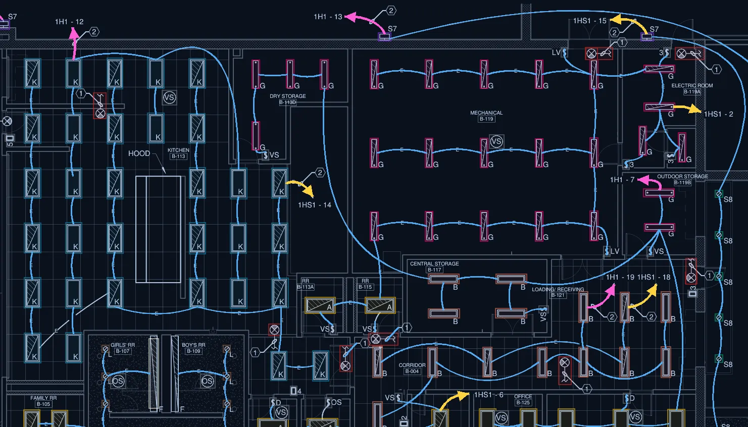
Branch circuits and home runs
On a lighting plan, fixtures on the same circuit are joined by arcs. Those arcs are the branch circuit: the conduit or cable that runs from fixture to fixture, and down to the switches and sensors that control them. At one end of each circuit, a short line with an arrowhead points toward the panel. That arrow is the home run, and its tag names the panel and the circuit.
On the example set, the tags read like 1H1-15 (panel 1H1, circuit 15) or 1HS1-14 (panel 1HS1, circuit 14). Two arrows can sit side by side and go to different panels: the figure shows 1H1-19 next to 1HS1-18. On some sets one tag lists several circuits that share a home run. Read the legend for your set; the convention is the engineer's.
Count the home runs by panel
Go sheet by sheet and list every home-run arrow with its tag. Group them by panel: the panel decides where each run ends, and so how long it is. In our run of the example sheet there were 32 home runs to 3 panels:
| Panel | Home runs on this sheet |
|---|---|
| 1H1 | 15 |
| 1HS1 | 14 |
| 1H2 | 3 |
| Total | 32 |
Then compare the list with the panel schedules. A lighting circuit with no home run anywhere in the set, or a home-run tag that is not a circuit on that panel, is worth a question before bid day.
Measure the home runs
The arrow on the lighting plan is the start of the home run, not the whole of it. To measure one:
- Find the panel. Look on the power plans, the electrical room enlargement or the riser diagram. The panels serving the example sheet are not drawn on it, so its drawn home-run arcs add up to 176.8 ft in all, a small part of the real length.
- Route it. Measure from the arrow to the panel along a route the conduit can take, usually along corridors and through accessible ceilings, not straight across rooms.
- Add the vertical. From the ceiling down to the panel, and any rise between floors.
- Add your makeup allowance at the boxes and in the panel, using your own standard.
Several home runs often leave an area together. Note where they could share a conduit, because the specification and the fill rules decide how many circuits one conduit may carry.
Measure branch conduit at the right scale
Branch conduit is measured along the circuit arcs, fixture to fixture. Before measuring anything, check the scale:
- Read the scale on the plan title, not the title block alone. The example sheet is 1/8" = 1'-0": one inch on the full-size sheet is eight feet.
- Check it against a known dimension, such as a dimension string, a column grid or a ceiling grid. Sets are sometimes printed or saved at half size, which halves every measurement if you trust the printed scale.
- Watch for enlarged plans at a different scale on the same sheet.
The arcs are diagrammatic. Real conduit follows the structure and the ceiling, so decide on a routing allowance for the measured length, and take it from your own job records rather than a rule of thumb.
In our run of the example sheet, 437 branch runs measured 3,721.9 ft of branch conduit along the drawn circuits at 1/8" = 1'-0".
Drops, whips and devices
The plan view hides the vertical work. Add it item by item:
- Switch and sensor drops: from the ceiling down to each wall switch, dimmer or wall sensor, at the ceiling height from the reflected ceiling plan and the mounting height from the specification.
- Fixture connections: lay-in fixtures are often connected with a flexible whip from a box above the ceiling, one per fixture; the specification sets the wiring method and any length limit.
- Pendants and high bays: the drop from the structure or the ceiling to the fixture.
- Ceiling sensors and power packs, and the low-voltage cable between them and the switches.
Count the conductors
Wire is conduit length times the number of conductors in each run, plus makeup. To get the number:
- Read the hash marks where the drawings use them. The example set's legend says "Long slash denotes neutral conductor, short slash denotes phase conductor", with another mark for an isolated ground.
- Where no marks are drawn, decide from the circuit, the switching and the specification.
- Add emergency circuits. On the example sheet, hex note 1 says emergency fixtures connect "to respective room emergency lighting circuit ahead of all switching/relays", which is extra wiring wherever a room has hatched fixtures.
- Add control wiring. The example set uses 0-10V dimmers, so dimmable fixtures need control conductors back to the dimmer as well as power.
On the example sheet, our run used two conductors plus a ground on every run (the default where no hash marks are read), which gave 11,696.1 conductor-feet before any length to the panels was added. Check that default against the drawings and the specification on your own jobs.
How InstantTakeoff does it
InstantTakeoff traces branch circuits and home runs from the circuit lines drawn on the plan, or builds them from circuit tags when no lines are drawn, and estimates them when neither is readable. Home runs are grouped by panel, footage is measured at the sheet's scale, and branch conduit, home-run conduit, the home-run count and wire go into the estimate as their own lines. When a panel is not on the sheet, the home-run line says the length to the panel still has to be set. You can draw a missing run or fix a wrong one, and the totals follow.
See the runs on one of your own sheets: try a sheet free. No signup, no card. Conduit and wire footage go out with the rest of the estimate in Excel and CSV or through the API, and if your estimating software needs a direct connection, ask us and we'll build it, often the same day.
Questions
What is a home run on an electrical drawing?
A home run is the run of conduit and wire from the last device or box of a circuit back to its panel. On plans it is drawn as a short line with an arrowhead pointing toward the panel and a tag such as 1H1-15, which on the example set means panel 1H1, circuit 15. Check the legend on your set, because conventions vary.
How do I measure a home run when the panel is on another sheet?
Find the panel on the power plan, the electrical room enlargement or the riser, then measure from the arrow to the panel along a sensible route (corridors and accessible ceilings), and add the vertical run down to the panel and your allowance for makeup at each end. The arrow on the lighting plan is just the start of the run.
How many conductors are in a branch run?
Read the hash marks if the drawings use them; the legend says what each mark means. On the example set, a long slash is a neutral and a short slash is a phase conductor. Where no marks are drawn, use the circuit, the switching and the specification to decide, and add control conductors where dimming or low-voltage controls need them.
Does InstantTakeoff trace wiring?
Yes. It traces branch circuits and home runs from the circuit lines drawn on the plan, or builds them from circuit tags, and estimates them when neither is readable. Conduit and wire footage go into the estimate, and you can draw or fix runs.